Sunday 22 May 2011
Wednesday 18 May 2011
Selective timer alarm. වෙලාව වෙනස් කලහැකි ටයිමරය
Description.
A timer circuit using IC 4060 is given here. The IC 4060 is a 14 stage binary counter with a built-in oscillator.R2, R7, C1 are the components that determine the frequency of the oscillator and the outputs will become high one after other and only one at a time. The last five outputs are only used here. The high pulses from the outputs are used to trigger the NE555 IC. Here NE555 is wired as a monostable multivibrator. The buzzer will produce the alarm when the output of IC2 goes high. The duration of the alarm depends on the components C3 and R5.The duration can be adjusted by varying the value of C3.The alarm will automatically turn OFF after the predetermined time. The trigger pin of IC2 will be normally positive. When the Q1 is forward biased by the positive pulse at its base from IC1, the capacitor C2 becomes charged and reduces the voltage at trigger pin of IC2.This triggers the IC.When the capacitor is fully charged the pin 2 becomes again positive.
The maximum duration from timer IC 4060 will be at pin 3. The times decrease by half in the pins 2, 3, 15, and 13 respectively. The timer duration can be varied by varying the
Circuit diagram with Parts list.
Notes.
- Use 6V DC for powering the circuit.
- Assemble the circuit on a good quality PCB.
- Mount the ICs on holders.
- The switch S2 can be a single pole five throw rotary switch.
- The switch S1 can be a push button switch.
- S1 is used to reset the timer.
- S2 is used to select the alarm time.
- R7 can be used for the fine adjustment of alarm time.
Tuesday 17 May 2011
Power saving LED lamp from your scrap box. බිදිගිය සි එෆ් එල් බල්බයක කවරයක් ආධාර කරගෙන සුදු එල් ඊඩි භාවිතයෙන් විදුලිබලය ඉතිරිකරන බල්බයක් සාදාගමු
Power saving LED lamp from your scrap box.බිදිගිය සි එෆ් එල් බල්බයක කවරයක් ආධාර කරගෙන සුදු එල් ඊඩි භාවිතයෙන් විදුලිබලය ඉතිරිකරන බල්බයක් සාදාගමු
In this article he is showing a method to convert a broken/defunct CFL into a LED based power saving light.
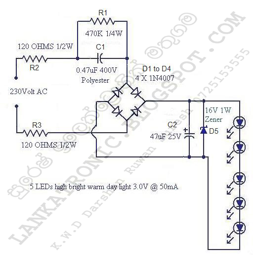
The is just a LED lamp circuit that can be operated from the mains voltage. A string of five LED is driven using a capacitive transformer less power supply. In the circuit 0.47uF/400V Polyester capacitor C1 reduces the mains voltage. R1 is a bleeder resistor which drains the stored charge from C1 when the AC input is switched OFF. Resistors R2 and R3 limits the inrush of current when the circuit is switched ON. Diodes D1 to D4 forms a bridge rectifier that rectifies the reduced AC voltage and C2 acts as a filter capacitor. Finally Zener diode D1 provides regulation and the LEDs are driven.
Photos.


Circuit diagram.
පටුන
LED LIGHT Circuit එල්ඊඩි විදුලි පරිපත
1.Power saving LED lamp from your scrap boxබිදිගිය සි එෆ් එල් බල්බයක කවරයක් ආධාර කරගෙන සුදු එල් ඊඩි භාවිතයෙන්විදුලිබලය ඉතිරිකරන බල්බයක් සාදාගමුTimer Circuit ටයිමර් සකිටි
Subscribe to:
Posts (Atom)